Product Introduction
1、 Cleaning machine function a. Cleaning power of the cleaning machine: 1000W (with 10 U-shaped mercury lamp tubes containing 100% ozone and 100 watts/lamp); b. Cleaning area: The maximum is 500 × 500m m2, and the cleaning area can be set in different zones as needed. (The panel is equipped with a switch corresponding to each lamp, which can manually stop any one or any few lamps from working without alarm.);
technical parameter
1、 Cleaning machine function
a. Cleaning power of the cleaning machine: 1000W (with 10 U-shaped mercury lamp tubes containing 100% ozone and 100 watts per lamp);
b. Cleaning area: The maximum is 500 × 500m m2, and the cleaning area can be set in different zones as needed. (The panel is equipped with a switch corresponding to each lamp, which can manually stop any one or any few lamps from working without alarm.);
c. Working state: GXT-SP cleaning machine has two working states, which can be manually selected, or half power mode, or automatic power-off mode. State 1: Automatic power-off mode - Full power start, automatic power-off when cleaning time is up; State 2: Half Power Mode - Full Power Start. When the cleaning time is up, the buzzer will emit two intermittent beeps and switch to half power operation. The switching of working state is provided by the two switchable dimming functions of the ballast that drives the lamp tube. The 150W ballast that drives each lamp tube is dimmed in two levels, with an illumination of 100% during operation and 30% during half power. Only when working in half power state, when the working time is up, the cleaning machine is in half power working state (there is no half power working in automatic power-off state). Regardless of the working state, when the material platform drawer is pulled out of the cabinet, the light will automatically reduce to half power operation
d. Real time monitoring of tray and air outlet temperature to monitor the ventilation inside the machine;
e. The cleaning time can be pre-set:<1 hour (with a one hour full range timer device that can be manually set as needed);
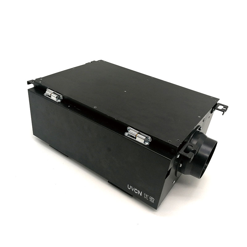
f. There is an exhaust device installed inside the machine, which can forcibly and quickly discharge the ozone inside the machine;
g. The air intake is forced to ventilate by a 12v, 15W fan, and the air is filtered through a filter before entering the machine;
h. Replacing the lamp tube and cleaning the filter screen are relatively convenient.
I. Alarm function: When there is a light tube inside the device that does not light up, it will give an audible and visual alarm (buzzer and red LED light); When an alarm occurs, the LED light located in the upper right corner of the panel can indicate which light is faulty, and the buzzer emits a continuous alarm sound;
j. Automatic alarm reset function: When a fault exists and continuous alarms are triggered, the alarm reset button can be pressed once to stop the alarm sound. Press again to restore the alarm sound;
k. The observation hole is located on the drawer panel of the material and is equipped with a glass observation hole, which can observe the ultraviolet light during cleaning from outside the cabinet
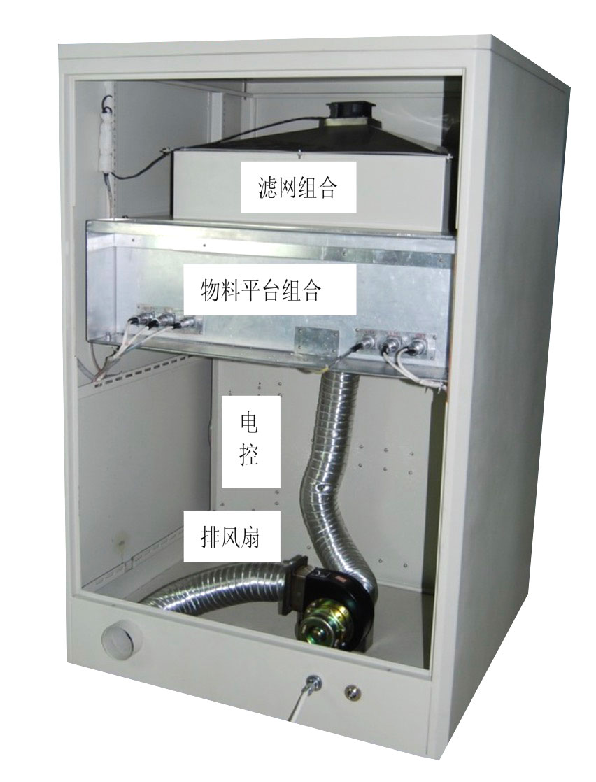
2、 The main components of GXT-SP cleaning machine
The GXT-SP cleaning machine is divided into four parts:
a. Material platform;
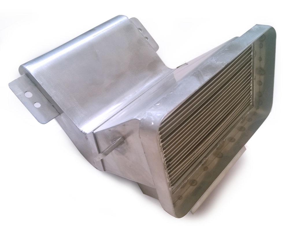
b. Filter combination;
c. Electronic control part;
d. Exhaust device.
3、 Operation and usage of cleaning machine
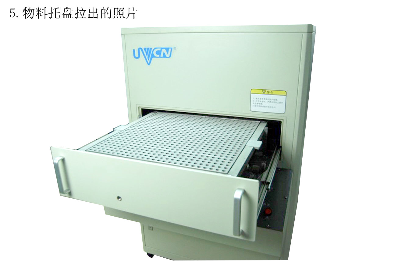
1. Cleaning and startup preparation work 1.1 Adjusting the height of the material platform, the operation method is as follows:
Steps for adjusting the height of the material platform
a. Open the material drawer (fully pulled out);
b. Grasp the handles on both sides with both hands, twist the handles forward or backward with both hands, and adjust the height of the platform in the same direction;
c. There is a ruler in front of each of the left and right handles, and the scale on the platform is aligned with the ruler, which is the distance from the platform surface to the surface of the lamp tube (usually the two rulers should indicate the same).
d. The adjustment range of the distance between the light source and the material of this machine is 10-40mm
1.2 Setting cleaning working hours
1.2.1 Timer Setting
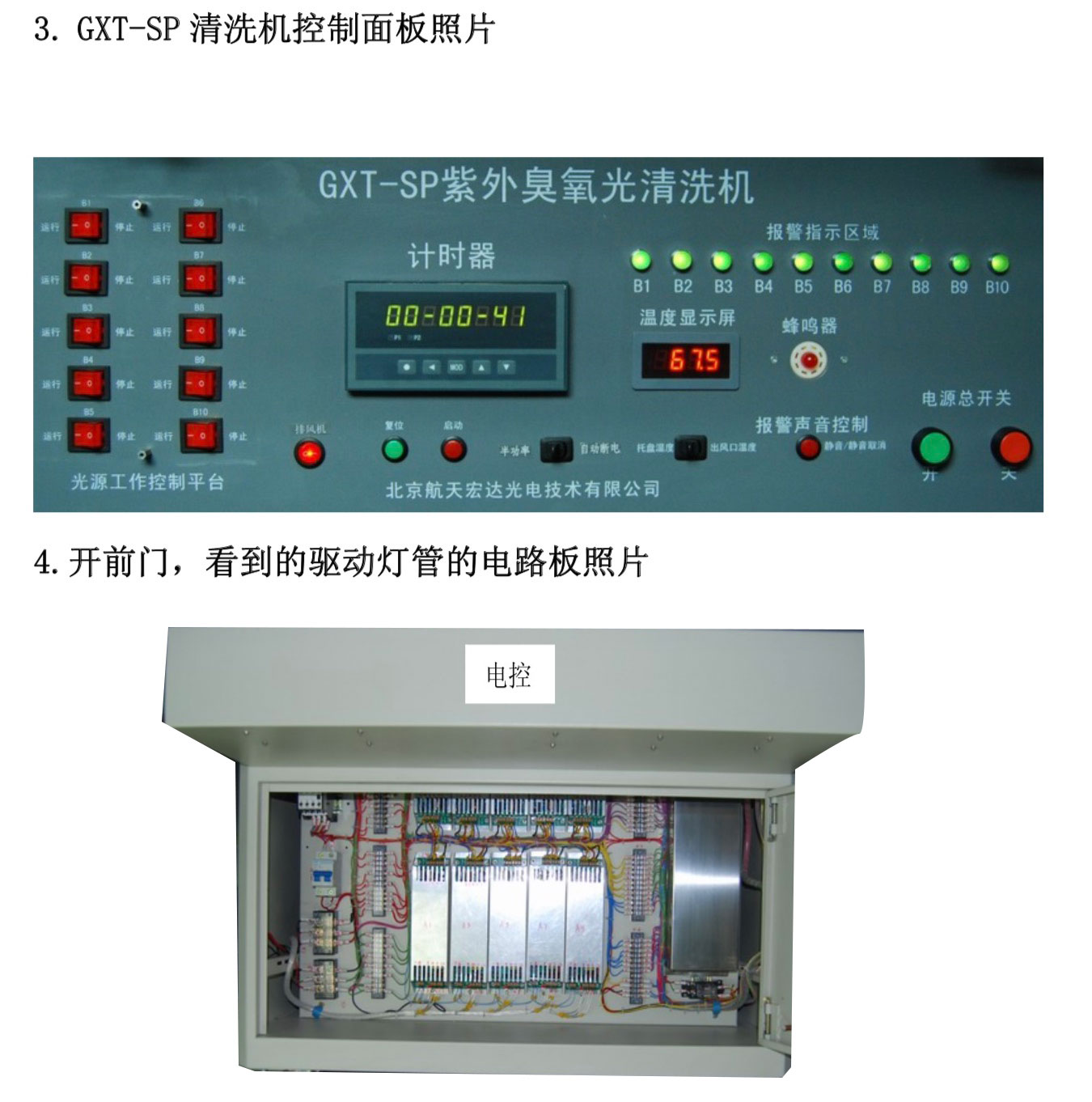
The working time of the cleaning machine is set by the timer on the panel.
Let's first introduce the setting of the timer: The timer panel is shown in the following figure
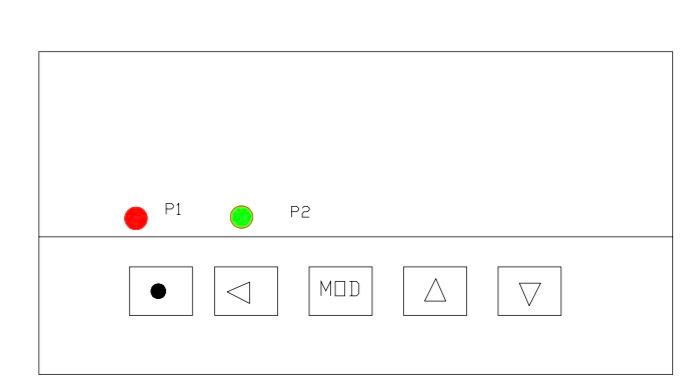
a. Timer parameters are divided into three groups, and we only consider the first and second groups of parameters Group 1: Timing Settings
HIA: t1 time FIA: t1 minutes SIA: t1 seconds
HIB: t2 hours FIB: t2 minutes SIB: t2 seconds
Group 2: Working Mode Settings
(oA): The password is valid when set to 1111.
(STA): Startup mode setting. Method 0:0000; Method 1: 0001
(YC): External reset setting. YC:ON
(SC): Manual reset setting. SC:ON
b. Parameters and Setting Methods
first:
Open the front door, close the air switch located at the bottom left of the circuit installation board, and connect it to AC 220V;
Secondly, press the main power switch on the panel;
Then: Set parameters
Step 1: Select the parameter group and hold down the setting button for more than 2 seconds without releasing it to enter the first set of parameters,
Press and hold the 'Set' button for more than 2 seconds without releasing it to enter the second set of parameters.
Step 2: Press the MOD key to select each parameter in the same parameter group
Step 3: Press the key to retrieve the original setting value of the parameter
Step 4: Use the ← key to move the modification position (flashing position), the ▲ key to add, and the ▼ key to subtract to modify the parameters.
Step 5: Press the MOD key to save the modified parameters
Step 6: Exit: Press and hold the · key in parameter code mode until you exit the parameter setting state
c. Timer working mode
Set the timer start mode to external trigger mode and reset mode to external control reset.
Startup mode - When the STA parameter is 0001, it can be started by the startup switch on the panel. Press the start switch on the panel to start the timer.
Reset method - Reset refers to restoring the timer to its state before starting. When the YC parameter is set to ON, it can be reset by the panel's reset switch for more than 1 second.
1.2.2 Setting of working hours
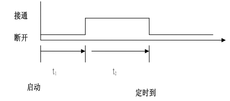
In the following figure, t1 represents that after pressing the "start" button of the timer, the timer starts counting after a 1-second delay. T2 represents the cleaning working time.
We set t1 to 0 and t2 to the material cleaning time.
1.3 Set the system working mode as needed: Set the switch in the middle below the panel to "half power" or "automatic power-off";
The material cleaning is in an intermittent step working state. Generally speaking, when there is a long interval between each material cleaning, the "automatic power-off" working state should be selected; If the interval between each time is short, the "half power" state can be used (this is beneficial for reducing the number of times the lamp is turned on and off, which is beneficial for improving the lamp's usage time. However, it should be strictly followed, and anti UV glasses should be worn before opening the drawer and replacing cleaning items. It should also be noted that gloves should be worn when extracting the material platform board to prevent overheating).
1.4 Select Material Cleaning Area
Select the required material cleaning area based on the area and degree of contamination of the product. Set the corresponding switch on the left side of the panel to the running state.
1.5 Press the exhaust fan switch, set it to "1", and turn on the exhaust fan.
2. Normal operating steps for the cleaning machine
Step 1: Complete all the preparation work in section 1;
Step 2: Press the "start" switch of the timer;
Step 3: When the timer reaches its working time and is in "automatic power-off" mode, the device will automatically power off, cutting off all AC and DC power to the entire host except for the exhaust fan. Generally, turn off the exhaust fan after five minutes (adjust this time according to the speed of ozone discharge).
When in the "half power" state, when the timer reaches its working time, the buzzer will emit two intermittent beeps and the red light will flash. At this time, the exhaust fan should continue to blow air.
3. Faults and troubleshooting methods
After accurate fault diagnosis, the ballast or lamp should be replaced.
b. Cannot power on
When the power switch is pressed, the device runs out of power. Firstly, the front door should be opened to check the air switch and power plug.
If not, power should be cut off to check the power supply line.
c. If the temperature gauge on the panel indicates that the tray temperature is too high (above 600C), it means that the equipment ventilation is blocked, and the air filter and exhaust duct should be cleaned in a timely manner.
4. Steps for adjusting the height of the material platform
a. Open the material drawer (fully pulled out);
b. Grasp the handles on both sides with both hands, twist the handles forward or backward with both hands, and adjust the height of the platform in the same direction;
c. There is a ruler in front of each of the left and right handles, and the scale on the platform is aligned with the ruler, which is the distance from the platform surface to the surface of the lamp tube (usually the two rulers should indicate the same).
d. The adjustment range of the distance between the light source and the material of this machine is 10-40mm
5. Steps for replacing the lamp tube: During the material cleaning process, if the lamp tube does not light up or ages, it should be replaced. a. Unscrew the four M 5 * 55 fixing screws on the top cover of the cabinet and remove the top cover;
b. Unscrew the M 6 × 20 six fixing screws of the filter combination above the cabinet, remove the filter combination, and all ten light tubes will be visible;
c. One end of each lamp tube is hung on a dedicated screw with a spring, and the other end is fixed to the lamp head with a M3 screw. Remove the spring, unscrew the screw, and then remove the lamp tube;
d. Use this method to remove any lamp tube;
e. According to the opposite order of d and c above, the new light tube can be installed;
f. After replacing the light tube, install the filter assembly and cabinet top cover in reverse order of b and a.
6. Operation steps for cleaning and replacing the filter screen: During the material cleaning process, if the temperature of the tray rises (generally below 600C), the filter screen must be cleaned. The temperature of the tray can be seen from the temperature gauge on the panel.
a. Remove the top cover of the cabinet according to the operation method in item a. of section 1.2;
b. Remove the filter combination according to the operation method in item b. of section 1.2;
c. Remove the seven screws connecting the filter screen assembly, move away the pressure plate, and move away the wind cover;
d. Take out the filter with both hands;
e. Clean the filter screen with a vacuum cleaner (or replace it with a new one. The size of the filter screen is: aluminum frame non-woven fabric 595 × 595 × 46mm);
f. Using the reverse operation of items e and c, install the filter combination properly;
g. Fix the filter combination on the platform frame with six screws;
h. Secure the cabinet top cover with four screws. Attention: The reflector is fixed under the filter combination, and precautions should be taken to prevent scratches during operation.
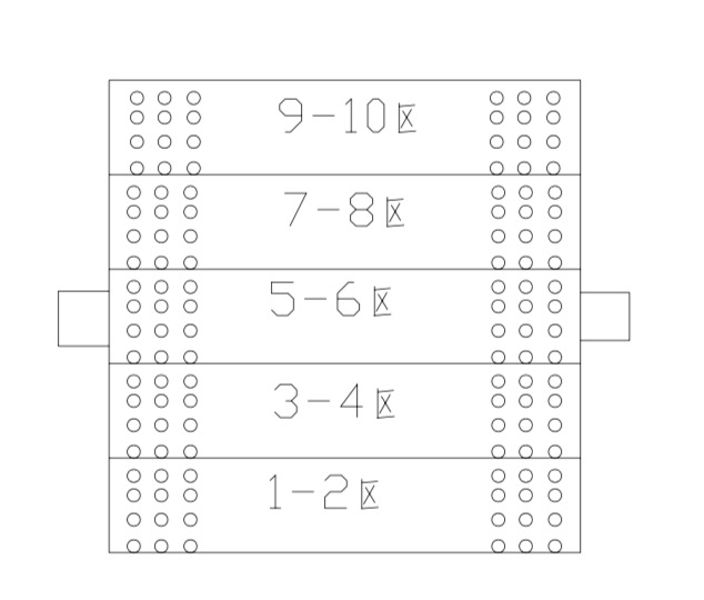
7. Instructions for object placement: The maximum cleaning area of GXT-SP cleaning machine is 500 × 500mm2. To achieve the optimal efficiency ratio, this cleaning machine can perform any partition cleaning through the ten switches on the panel. The following figure shows the area division of the object platform:
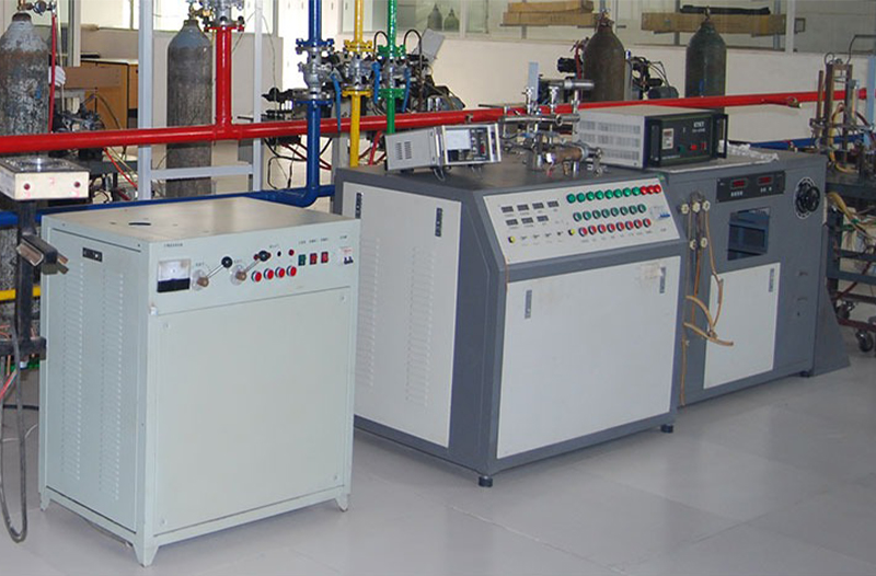
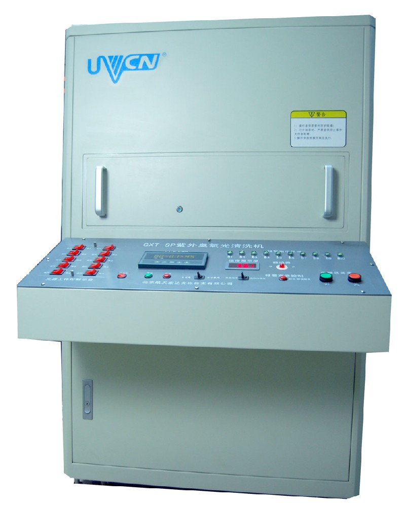
Overall photo of GXT-SP cleaning machine from the front

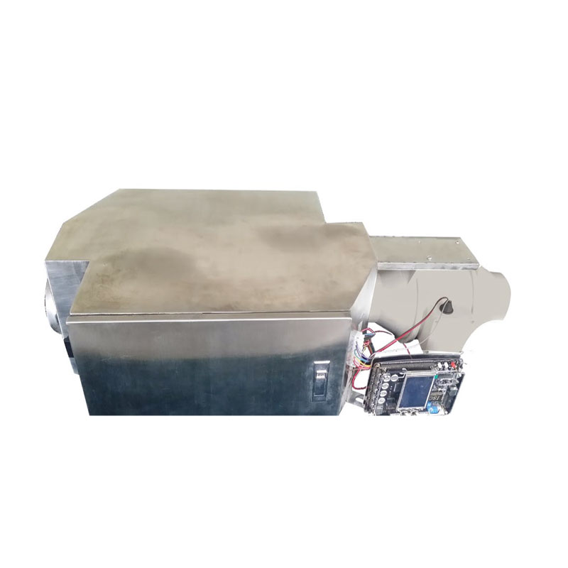
2. After removing the rear door, take a full picture of the GXT-SP cleaning machine

Long Press to Scan QR Code
Scan QR Code